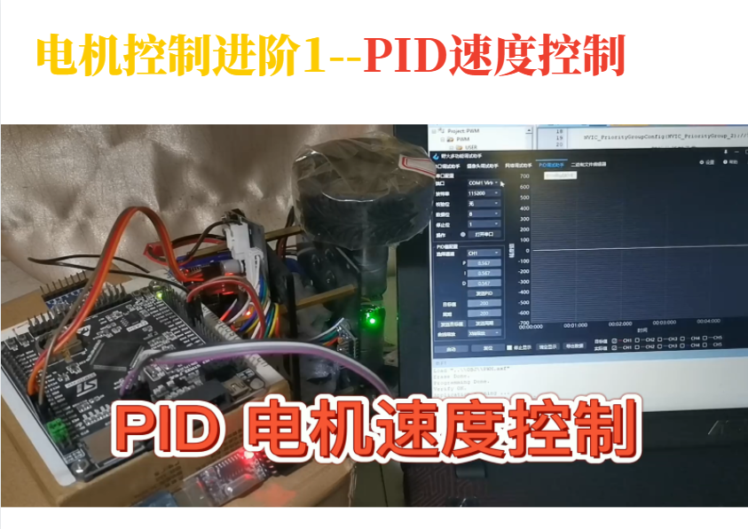
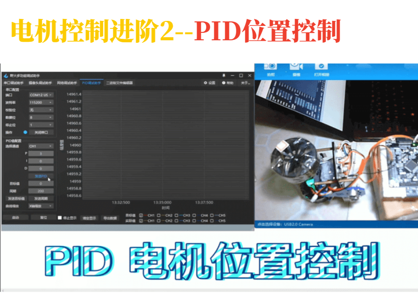
前两篇文章,分别介绍了PID速度控制和PID位置控制,分别用来控制电机以期望的速度持续转动以及以期望的位置(圈数)转动,这里的期望值都只有一个,但是,如果想要以期望的速度转动到期望的位置(启动与停止的加减速过程不考虑),该怎么控制呢?那就要将两者结合起来了,即PID的串级控制来控制电机。
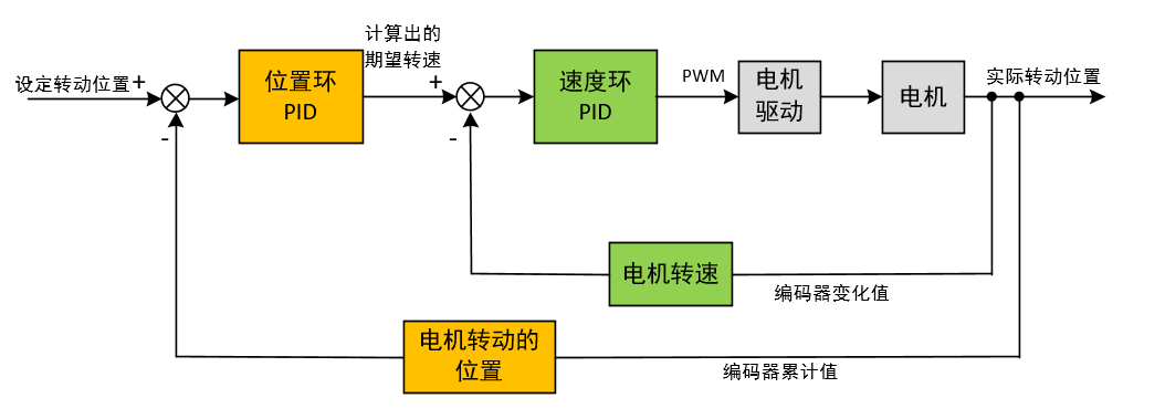
串级PID结构图
PID串级控制的典型结构为位置环+速度环+电流环,如下图。
PID串级控制中,最外环是输入是整个控制系统的期望值,外环PID的输出值是内环PID的期望值。
能够使用三环控制的前提是要硬件支持,比如位置环和速度环需要实时的电机转动位置和转动速度作为反馈,这就需要电机需要配有编码器用于测速与测量转动的位置;电流环需要有电流采样电路来实时获取电机的电流作为反馈。

如果没有电流采样电路,可以将电流环去掉,只使用位置环+速度环,系统的期望仍是转动的位置,内环可以调节转动的速度。
另外,如果只是想控制电机转速实现电机调速,可以使用速度环+电流环,系统的期望仍是转动的位置,内环可以调节电机的电流,增强系统转动调节的抗干扰能力。

位置环+速度环实践
由于我的电机没有电流测量电路,所以,本文以位置环+速度环来学习PID串级控制。就是按照下面这个图:

PID参数定义
由于是串级PID控制,每一级的PID都要有自己的参数,本次实验使用位置PID+速度PID,参数定义如下:
1
2
3
4
5
6
7
8
9
10
11
12
13
14
15
16
17
18
19
20
21
22
23
24
25
26
27
28
29
30
31
32
33
|
PID pid_location;
PID pid_speed;
void PID_param_init()
{
pid_location.target_val = TOTAL_RESOLUTION*10;
pid_location.output_val = 0.0;
pid_location.err = 0.0;
pid_location.err_last = 0.0;
pid_location.integral = 0.0;
pid_location.Kp = 0.05;
pid_location.Ki = 0;
pid_location.Kd = 0;
pid_speed.target_val=10.0;
pid_speed.output_val=0.0;
pid_speed.err=0.0;
pid_speed.err_last=0.0;
pid_speed.integral=0.0;
pid_speed.Kp = 80.0;
pid_speed.Ki = 2.0;
pid_speed.Kd = 100.0;
}
|
位置PID的实现
这里有两点需要注意:
闭环死区的设定
闭环死区是指执行机构的最小控制量,无法再通过调节来满足控制精度,如果仍然持续调节,系统则会在目标值前后频繁动作,不能稳定下来。
比如某个系统的控制精度是1,但目标值需要是1.5,则无论怎么调节,最终的结果只能控制在 1或 2,始终无法达到预设值。这 1.5L小数点后的范围,就是闭环死区,系统是无法控制的,误差会一直存在,容易发生震荡现象。
对应精度要求不高的系统,可以设定闭环死区,比如将允许的误差范围设为0.5,则最终结果在 1或 2都认为是没有误差,这时将目标值 与实际值之差强制设为 0,认为没有误差,即限定了闭环死区。
积分分离的设定
通过积分分离的方式来实现抗积分饱和,积分饱和是指执行机构达到极限输出能力了,仍无法到达目标值,在很长一段时间内无法消除静差造成的。
例如,PWM输出到了100%,仍达不到期望位置,此时若一直进行误差累加,在一段时间后, PID 的积分项累计了很大的数值,如果这时候到达了目标值或者重新设定了目标值,由于积分由于累计的误差很大,系统并不能立即调整到目标值,可能造成超调或失调的现象。
解决积分饱和的一种方法是使用积分分离,该方法是在累计误差小于某个阈值才使用积分项,累计误差过大则不再继续累计误差,相当于只使用了PD控制器。
控制流程图
带有闭环死区与积分分离的PID控制流程如下图:

完整的位置PID代码如下:
1
2
3
4
5
6
7
8
9
10
11
12
13
14
15
16
17
18
19
20
21
22
23
24
25
26
27
28
29
30
31
32
33
34
35
36
37
38
39
40
41
42
43
44
45
46
47
48
|
#define LOC_DEAD_ZONE 60
#define LOC_INTEGRAL_START_ERR 200
#define LOC_INTEGRAL_MAX_VAL 800
float location_pid_realize(PID *pid, float actual_val)
{
pid->err = pid->target_val - actual_val;
if((pid->err >= -LOC_DEAD_ZONE) && (pid->err <= LOC_DEAD_ZONE))
{
pid->err = 0;
pid->integral = 0;
pid->err_last = 0;
}
if(pid->err > -LOC_INTEGRAL_START_ERR && pid->err < LOC_INTEGRAL_START_ERR)
{
pid->integral += pid->err;
if(pid->integral > LOC_INTEGRAL_MAX_VAL)
{
pid->integral = LOC_INTEGRAL_MAX_VAL;
}
else if(pid->integral < -LOC_INTEGRAL_MAX_VAL)
{
pid->integral = -LOC_INTEGRAL_MAX_VAL;
}
}
pid->output_val = pid->Kp * pid->err +
pid->Ki * pid->integral +
pid->Kd * (pid->err - pid->err_last);
pid->err_last = pid->err;
return pid->output_val;
}
|
速度PID实现
速度PID的实现代码与位置PID的类似:
1
2
3
4
5
6
7
8
9
10
11
12
13
14
15
16
17
18
19
20
21
22
23
24
25
26
27
28
29
30
31
32
33
34
35
36
37
38
39
40
41
42
43
44
45
46
47
48
|
#define SPE_DEAD_ZONE 5.0f
#define SPE_INTEGRAL_START_ERR 100
#define SPE_INTEGRAL_MAX_VAL 260
float speed_pid_realize(PID *pid, float actual_val)
{
pid->err = pid->target_val - actual_val;
if( (pid->err>-SPE_DEAD_ZONE) && (pid->err<SPE_DEAD_ZONE ) )
{
pid->err = 0;
pid->integral = 0;
pid->err_last = 0;
}
if(pid->err > -SPE_INTEGRAL_START_ERR && pid->err < SPE_INTEGRAL_START_ERR)
{
pid->integral += pid->err;
if(pid->integral > SPE_INTEGRAL_MAX_VAL)
{
pid->integral = SPE_INTEGRAL_MAX_VAL;
}
else if(pid->integral < -SPE_INTEGRAL_MAX_VAL)
{
pid->integral = -SPE_INTEGRAL_MAX_VAL;
}
}
pid->output_val = pid->Kp * pid->err +
pid->Ki * pid->integral +
pid->Kd *(pid->err - pid->err_last);
pid->err_last = pid->err;
return pid->output_val;
}
|
串级控制代码
1
2
3
4
5
6
7
8
9
10
11
12
13
14
15
16
17
18
19
20
21
22
23
24
25
26
27
28
29
30
31
32
33
34
35
36
37
38
39
40
41
42
43
44
45
46
47
|
void AutoReloadCallback()
{
static uint32_t location_timer = 0;
static __IO int encoderNow = 0;
static __IO int encoderLast = 0;
int encoderDelta = 0;
float actual_speed = 0;
int actual_speed_int = 0;
int res_pwm = 0;
static int i=0;
encoderNow = read_encoder() + EncoderOverflowCnt*ENCODER_TIM_PERIOD;
encoderDelta = encoderNow - encoderLast;
encoderLast = encoderNow;
if ((location_timer++ % 2) == 0)
{
float control_val = 0;
control_val = location_pid_realize(&pid_location, encoderNow);
speed_val_protect(&control_val);
set_pid_target(&pid_speed, control_val);
}
actual_speed = (float)encoderDelta / TOTAL_RESOLUTION * 10 * 60;
actual_speed_int = actual_speed;
res_pwm = pwm_val_protect((int)speed_pid_realize(&pid_speed, actual_speed));
set_motor_rotate(res_pwm);
set_computer_value(SEND_FACT_CMD, CURVES_CH1, &encoderNow, 1);
}
|
PID的计算是通过定时器调用,每10ms一次,从代码中可以看到,内环(速度PID)控制的周期要比外环(位置PID)的周期短,位置PID是每两次循环计算一次,因为内环控制着最终的输出,这个输出对应的就是实际场景中的控制量 (本实验最终控制的是位置),位置是无法突变,是需要时间积累的,所以内环输出尽可能快些。
视频演示
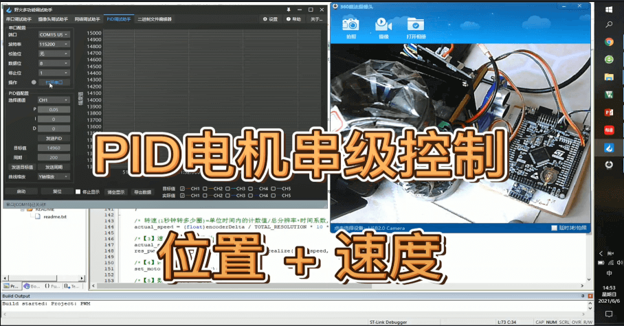
视频中,测试以不同的目标速度到达目标位置,视频后半段测试引入干扰情况下的控制效果:
视频:https://www.bilibili.com/video/BV1QK4y1g7yg
开源代码
本篇以及前面几篇电机与PID的完整程序代码,公众号回复“电机PID”获取,或到我的gitee仓库获取:https://gitee.com/xxpcb/stm32-motor-pid。
文章对你有帮助,欢迎转发支持哦~


